Table of Contents
TIG Welder
The Setup, Operation, and Cleanup Checklists sections of this guide are what instructors use to ensure that you can use the equipment according to community expectations.
TIG welding is a versatile method of welding that is considered one of the best ways to weld aluminum and thin steels. Though extremely precise welds are possible, TIG is often slower than other welding methods, and can be difficult to learn due to the coordination required. The welding torch held in one hand is used to melt the base metal, and then the tip of a filler rod held in the other hand is dabbed into the molten puddle to build up the weld. A foot pedal is used to initiate and extinguish the arc, and is also used to vary the amperage as needed to control the size of the weld puddle as it is pushed along the weld joint.
Usage Highlights
TIG Clearance or Class Equivalent Required Before Use
| SAFETY | CARE | CLEANUP |
| ———————————————– | ————————————————————————————————————- | ——————————————————- |
| 1. Wear proper PPE. | 1. Protect the welding table from arcing and spatter. | 1. Close the argon tank valve. |
| 2. Isolate the welding area with curtains. | 2. Secure the TIG torch when setting it down to prevent it from falling off the table and breaking the cup. | 2. Purge the pressure from the regulator. |
| 3. Do not touch electrically live components. | 3. Do not grind troughs into the grinding wheel. | 3. Return hoses, clamps, and fixtures to their homes. |
| 4. Submit a maintenance request when needed. |
Personal Protective Equipment
Welding Helmet shields the eyes from extreme light levels and harmful UV rays. Failure to protect your eyes will cause “welder’s flash” which at it’s mildest can cause inflammation or temporary blindness, and in severe cases, permanent blindness. Auto-darkening helmets can be set to ‘grind’ mode, which causes them to not activate, or to activate at a very low shade. Double-check your shade settings each time you begin an operation. Shade 11 is a common setting for arc welding. 10 should be the minimum shade used.
Safety Glasses should be worn beneath the welding helmet.
A long-sleeved welding jacket is made of leather or flame-retardant cloth which will help protect your skin from UV light and hot sparks. They should be worn any time you are welding.
Gloves will protect your hands from UV light and hot sparks. TIG gloves are thinner than other welding gloves in order to provide more dexterity, but they provide less protection when handling hot metal, and you can easily get burned through the gloves when handling freshly welded metal. Handling hot metal with leather gloves will also destroy the gloves. Use pliers to manipulate hot workpieces.
Close-toed shoes made of leather or natural fibers should be worn. Open shoes or shoes made of synthetic fibers (which will melt) will allow hot sparks to be trapped against your feet.
Tool Anatomy
MACHINE ANATOMY
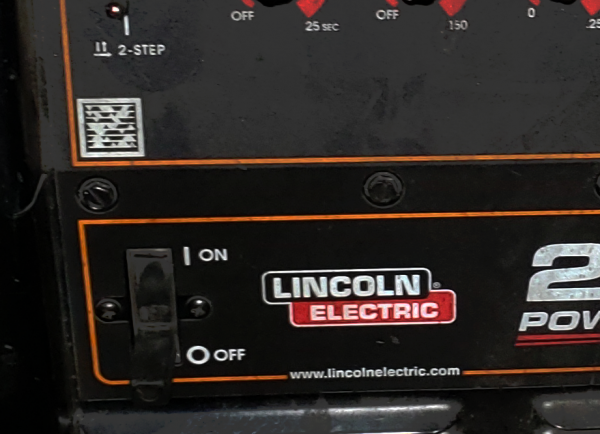
1. Power Switch - on/off switch
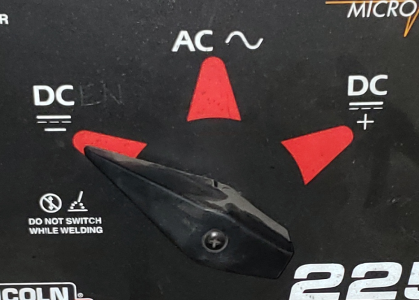
2. Polarity Selector - This selector allows the user to define whether the torch electrode is always negative (DCEN), always positive (DCEP), or alternates between positive and negative (AC). Most steel wil be welded in DCEN, and most aluminum will be welded in AC.
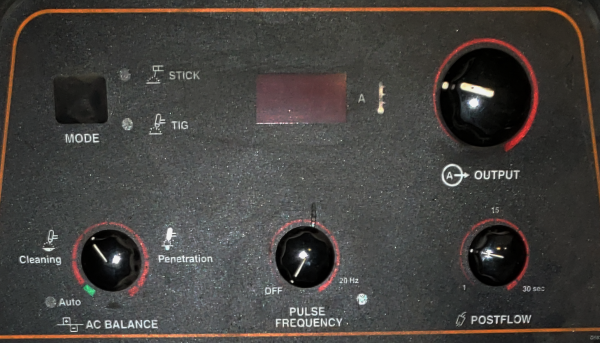
3. Output Knob - The amperage is set by the user, and dictates how much electrical current will pass through the arc.
4. Mode Selector - Put the machine in “STICK” or “TIG” mode. This should always be set to “TIG” when TIG welding.
5. AC BALANCE - When in AC mode (mostly for aluminum), determines the amount of time spent in DCEN (welding) vs DCEP (cleaning). The more time spent in DCEP the hotter the tungsten will become, but the more cleaning action will be apparent on the work piece. The cleaning action should be kept to a minimum, where it will adequately clear the aluminum oxide away from the weld puddle, but does not extend much further.
6. Pulse Frequency - The machine can automatically raise and lower the amperage in a repeating cycle. This can be useful when doing delicate work to help control heat.
7. Postflow - Amount of time to flow gas after the arc is terminated. Provides covering gas as the weld cools.
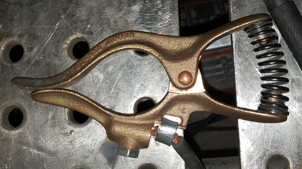
8. Ground Clamp - Sometimes referred to as the Work Clamp, this clamp is attached to the workpiece in order to complete the circuit from the electrode back to the welder. This must have good electrical contact with the workpiece in order to achieve a solid arc. Clamp directly to a bare metal part of the workpiece, since clamping this to the table will force the electrical current to jump from the workpiece to the table, and the workpiece will tend to weld itself to the table. Paint and rust will block the current from flowing.
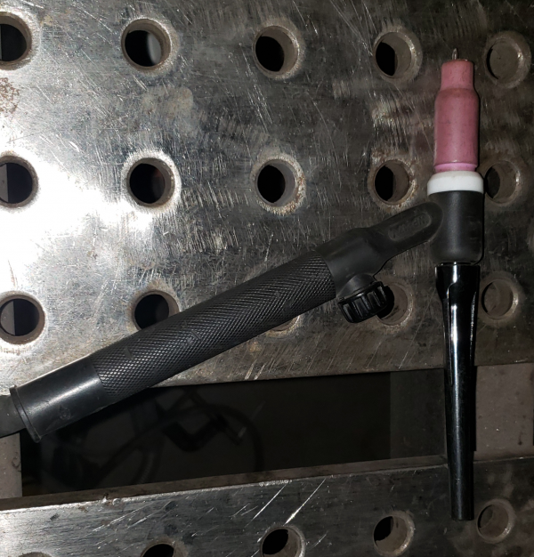
9. TIG Torch - Acts as the second electrode in the welding circuit. The torch assembly is made of the torch body, a collet, a collet body, a back cap, a cup, and the tungsten electrode.
10. Tungsten Electrode - The TIG torch uses a tungsten as an electrode, which is fairly heat resistant, especially compared to the other common welding techniques like MIG or stick welding. Tungsten electrodes come in different alloys and sizes. Mild steel and aluminum both weld well with lanthanated tungsten (purple) or ceriated tungsten (gray). Do not use thoriated tungsten (red) in the shop, as it is radioactive, and the grinding dust poses a health hazard to you and other members. Pure tungsten (green) is also available, but does not hold an arc as well as blended types. Using too small a diameter tungsten for a given amperage will cause it to melt, and using too large a diameter tungsten for a given amperage will leave it too cold to properly emit electrons, leading to unstable arc properties. AC and DCEP processes heat the tungsten more than DCEN, and may need a larger diameter to prevent melting the electrode.
11. Collet Holder - The collet holder screws into the head of the torch and encapsulates the collet when the torch is assembled.
12. Cup - The cup directs the shielding gas around the tungsten and towards the weld joint. It is screwed on to the collet holder after the collet holder is installed in the torch head.
13. Collet - The collet slides into the back of the collet holder, and when it is compressed against the inside of the collet holder it pinches the electrode and holds it firmly in place at its current length.
14. Back Cap - Screws into the back of the torch as the last part of assembly, and pushes the collet into the collet holder.
15. Maintenance Tag - Manually tracks the usability status with Green/Yellow/Red cards
Tool Safety
COMMON HAZARDS
Common hazards include electrocution, hot surfaces, sparks, UV light exposure, and toxic gasses.
To avoid electrocution, never open the side case without unplugging the machine. When operating the welder, make sure that the workpiece is properly grounded with the ground clamp, and that no part of your body is introduced into the circuit between the gun electrode and the workpiece. I.e. do not hold the wire against your hand and pull the trigger. Take care to maintain control over any filler wire that is ejected from the gun while purging the gas lines to prevent incidental contact with any person or nearby objects.
When working in the welding area, assume that any metal objects or surfaces are hot. A previous worker may have set down a hot piece of metal and walked away. Hover your hand over any piece to see if it is radiating heat before touching it. Use gloves and pliers as appropriate to move hot pieces.
Wear thick, natural-fiber clothing to keep sparks from contacting your skin.
UV light is especially harmful to your eyes, but can also cause damage to any exposed skin. Always wear a welding helmet with a shade of at least 10, and cover all skin surfaces. Make sure your workpiece is completely cleaned of any paints or coatings. Heat will travel quite a distance through the workpiece, so you must strip far more than just where you will be welding. Always position the fume hood where it can capture the welding fumes.
PROHIBITED MATERIALS
Workpieces that are painted, powdercoated, galvanized, or otherwise similarly coated should not be welded. Many solvents, especially those containing chlorine, are prohibited. If at all in doubt, use acetone and allow it to completely evaporate before welding. Toxic fumes can kill you and others nearby.
Thoriated tungsten electrodes are radioactive, and not permitted.
Initial Setup
SETUP CHECKLIST
Prepare your weld fitment
This is one of the most critical and time-consuming parts of the welding process. The parts to be welded must be ground down to bare, shiny metal, and be free of oils and debris.
A flap disc, grinder, or wire wheel is often used for this purpose. A flat, undamaged work-surface is necessary for precision fitups, so do not grind on the welding table without taking steps to protect the table from incidental grinder contact if you must grind in the welding area. The pieces should fit together snugly; it is possible to fill in gaps with weld, but it is less-than-ideal. When joining material thicker than ¼”, the edges will likely need to be beveled in order to achieve a deep, strong weld.
Grinding wheels and wire brushes dedicated to aluminum should not be used to clean steel. Small bits of the steel will become embedded in the wheel or brush, and will contaminate any aluminum it is used on in the future. Contamination of this type can lead to rust spots and weld failure.
Prepare Your Tungsten
The tungsten will need to be periodically sharpened as it will become contaminated if it touches the weld puddle or if it overheats and loses its shape. Even a perfectly cared tungsten will eventually need to be resharpened due to natural erosion or “burnoff” that occurs over time during welding. The exact angle of the grind is not critical for hobby level work, but does have an effect on arc stability and tungsten longevity. Generally, a pencil-tip is adequate. The very tip may be ground flat to increase longevity, or left sharp to increase arc starting and stability. Always wear safety glasses when grinding. Hold the tungsten so the grind marks are along the length of the tungsten, not across it. Do not create deep grooves in the grinding wheel, even though it makes for an easy surface, as it weakens the wheel and it may shatter explosively. Stand to the side of the wheel to avoid debris. If a tungsten has been contaminated by being dipped into the weld puddle, snap off the end to avoid contaminating the grinding wheel with non-tungsten materials. Do not try to cut the tungsten with wire cutters, as it will damage the cutters. It is safer to ‘drag’ the point as you grind, so the point does not catch on the wheel and drive it towards the operator. If grinding against the tip, DO NOT hold the tail end against your palm, or the tungsten can be driven through your hand.
Assemble the Torch
1. Screw the collet holder onto the front of the torch (the side with the white ring). This should be firmly finger-tight.
2. Screw the cup onto the collet holder. This should be tightened enough to close the gap between the cup and the white plastic ring, but gently, as overtighening can cause the white ring to shear off of the torch.
3. Insert the collet into the back of the torch. It should drop completely into the collet holder.
4. Insert the tungsten into the collet from the back of the torch. The sharpened end should go through the torch and come out the front of the cup. The fine adjustments to how far the tungsten sticks out from the torch will be adjusted later.
5. Screw on the back cap until it just starts to provide resistance. If you are using a new tungsten, you must use a long back cap to encapsulate the entire length of the rod. If you are using a mostly used-up rod, a shorter back cap can be used to reduce the profile of the torch.
6. While the back cap is only partially tightened, there should be enough resistance between the collet and the tungsten that you can adjust the length of the tungsten by grabbing the point with your fingers and moving it in and out of the torch. Move it so that the tungsten protrudes roughly two times the diameter of the tungsten rod.
7. Tighten down the back cap firmly to lock the tungsten in place.
Secure your Workpieces
Immobilize your work using clamps, magnets, or other fixturing devices. Give enough room between your weld area and the fixtures to prevent damaging them while welding.
Put on your PPE
Find a welding helmet and adjust the head band so it fits securely on your head. Double-check to make sure the shade level is 10 or higher, and that grind mode is not activated. Wear safety glasses under your hood. Make sure you cover all skin surfaces by wearing MIG gloves, a welding jacket, long pants, and shoes made of natural fibers (leather boots preferred).
Position the workspace protection
Make sure the welding curtains block all possible line-of-sight from the arc to other parts of the shop. Other users of the shop may not be aware that the welding arc may damage their vision.
Position the fume extractor above or next to where you will be welding. You should move this frequently for maximum effectiveness as your welding position changes.
Open the gas tank
Make sure the regulator knob is backed off so there is no tension on the spring. Do not unscrew it so far that the knob comes out of the regulator.
Very slowly open the tank valve. In rare instances the valve itself has been blown off of the top of the tank while being opened. Do not place your hand on top of the valve handle to avoid serious injury if this were to occur. Opening the tank valve too quickly can shock the regulator, rupturing the diaphram and throwing debris at the operator. Stand to the side of the regulator so as to be out of the most likely path of debris if the regulator were to rupture. Once the tank pressure needle begins to move, stop opening the valve and allow the regulator to pressurize. The right gauge should read somewhere between 100 and 2000 psi. If the gas is low, please submit a maintenance request to swap the tanks. Once the regulator has pressurized, open the valve at least two turns to allow proper gas flow.
Once the tank valve has been opened, slowly screw in the regulator knob until the desired working pressure on the left gauge has been achieved. Note that the pressure may drop slightly while shielding gas is actively being dispensed by the welder. Adjust the regulator so that the proper shielding gas coverage will be achieved while actually welding. A common setting for TIG welding is 15cfh. Please be conservative with your setting, and only use as much flow as is needed to get adequate coverage. Too much gas flow can actually draw atmospheric air with it, contaminating the weld. Imagine the gas creating a small pillow of air surrounding the weld, rather than a rush of air blowing over it.
Turn on the welder and adjust the settings
Turn the power switch to “ON”. Using the chart of established settings found on the welder’s case, determine the proper amperage and adjust the machine appropriately.
COMMON SETTINGS
For a ballpark amperage setting, use one amp for every .001”. E.g. a ⅛” thick plate would be .125” thick, so an amperage of 125 would be about right.
Filler rods should be thinner than the material being welded, but the smaller the diameter, the faster you will have to feed.
Tungsten diameter needs to be large enough that the electrode does not melt, but using too large an electrode will degrade the arc quality.
CONSUMABLES
Members are responsible for purchasing and maintaining their own tungsten electrodes. The shop will make every effort to have available standard collets, collet holders, and cups, but serious welders may wish to bring their own.
A small selection of steel and aluminum filler rods are available to purchase from the store, but serious welders may wish to bring their own supply.
Basic Operation
OPERATION CHECKLIST
Check ground clamp
Ensure that your ground clamp has good electrical contact with your workpiece. It should be attached to bright, clean metal.
Position torch
Hold the torch so the tip of the tungsten electrode is 1/8” from and perpendicular to the workpiece. Angle the tip of the torch 10 degrees towards the direction of travel.
Position filler rod
Hold the filler rod in our other hand at a low angle over the intended weld path, pointed towards the torch’s electrode. This will let you access the weld puddle under the leading edge of the torch cup. You should aim to maintain about three inches of filler rod between your feeding hand and the weld puddle.
Check your position
Before welding, you should check to make sure that you have free and smooth access to the weld joint along its entire length. Making a dry run will often bring interference and entanglement issues to your attention.
Lower your hood
With a quick nod of your head, drop the hood over your face.
Announce that you are "WELDING"
Ensure that anyone in the area knows that you are about to initiate an arc by announcing that you are “Welding”. This gives them time to avert their eyes if they are unprepared, and lets people who may be about to enter the area that it is unsafe to do so.
Tack the ends of the joint
Make a small tack weld at the start and end of the weld joint you are about to make. This prevents the pieces from shifting or drifting apart during the weld due to heat movement. You should inspect these welds and clean off any soot before continuing.
Initiate an arc
Depress the foot pedal all the way to initiate an arc. The electrode should stay at a consistent height and should not move.
Establish a weld puddle
Once the arc is initiated, holding it in one place over the workpiece will add heat where the arc contacts the metal. When the metal melts, it will become smooth and shiny, forming a small pool of molten metal.
Add filler rod
Once a weld pool has formed, lightly dip the tip of the filler rod into the leading edge of the pool. You do not want to melt the rod with the arc, but rather let the pool absorb the filler rod directly. Be careful not to let the tungsten electrode touch the puddle, as the fluid level will rise as material is added. Pull the filler rod back away slightly from the pool, but keep it close enough that it stays within the envelope of shielding gas from the torch.
Move and repeat
After adding a dab of filler rod, move the torch slightly forward along the weld joint in order to melt the next bit of metal in the direction you are welding. Pause and wait for the molten puddle to follow the path of the torch and establish itself under the arc. Add another dab of filler rod as before.
Terminate the weld
When you reach the end of the weld joint, the build-up of heat in the workpiece may be significant, and you will likely need to taper off on the foot pedal in order to decrease the heat of the arc as you come to the end of your weld. As you reach the termination point, pause briefly with the arc still active and add a bit of additional filler rod at the end of the weld. Without adding this additional fill, the end of your weld will develop a slight crater in it as the molten puddle cools and shrinks. That crater will be a weak spot in the weld, and may lead to cracking and failure of the joint.
Wait
After extinguishing the arc, pause for a moment and let the puddle cool before continuing. The TIG machine is equipped with post-flow, which keeps the shielding gas flowing for a short time after the arc has been extinguished. Keeping the hot weld shielded until it is no longer glowing is critical to keeping the weld uncontaminated.
Clean the weld and inspect
Look the weld over for signs of porosity, proper fusion at both sides of the weld, and an appropriate bead profile. Use a wire brush to clean off any soot and silicon deposits.
Cleanup
Cleanup CHECKLIST
Close tank and purge regulator
Turn the tank valve handle clockwise until it is firmly seated in the closed position.
The residual pressure must be purged from the regulator to prevent damage to the springs and diaphragm. Point the torch in a safe direction where it won’t contact any person or objects and depress the foot pedal. After a few seconds the gas pressure gauges should both drop to zero.
Once the gauges are at zero, turn the pressure regulation knob counterclockwise until there is no tension being put on the diaphragm by the knob. The knob should not be unscrewed completely from the regulator.
Turn off welder
Flip the power switch to ‘OFF’.
Store the leads
Coil the ground and torch leads loosely and drape them over the handle of the welder. Remove your tungsten from the torch once it has cooled. The rest of the torch may be left assembled, but care should be taken not to drop or damage the delicate ceramic cup.
Clean up clamps
Gather any clamps, magnets, and fixtures on the welding tables and return them to the tool cart.
Sweep the floor
Use a broom to sweep the entire welding area, collecting any grinding dust, filler wire, and cut-offs that may be on the floor.
Scrap
There is a small scrap bin under the cutting table into which recyclable steel may be placed.
MAINTENANCE REQUESTS
1. Update the physical Maintenance Tag at the machine
- Green can be used without issue
- Yellow can be used with caution
- Red cannot be used without hazard to either the user or the equipment
2. Record issues at protohaven.org/maintenance. This notifies our staff and volunteer maintenance crew of any issues
Troubleshooting
| Common Issues | Possible Causes | RESOLUTIONS |
| ——————————————————————————— | ————————————————————————— | ——————————————————————————————————————————————————————————————————————- |
| Excessive soot and porosity. | Inadequate or excessive gas flow. Excessive stickout. | Check that the gas cylinder valve is open and there is pressure. Check that the gas flow is set to between 13 and 18 cfh. Listen for gas flow when the pedal is depressed. Hold the electrode closer to the work. |
| Arc is crackling, spitting, and wandering. Tungsten is no longer pencil-shaped. | Tungsten is contaminated. | Remove electrode from torch and resharpen. |
| Arc will not initiate. | Inadequate ground. Insufficient pedal. Improper amperage. Torch too high. | Position the ground closer to the weld. Attach the ground clamp to bright, clean metal on the workpiece. Push pedal all the way to the floor. Increase amperage. Hold torch closer to work. |
| The workpiece is getting too hot | The arc length is too long. | Hold the electrode closer to the puddle. |
Additional Resources
Staff-Use
AUTHORIZED MAINTENANCE CREW ONLY
If you are part of the maintenance group please log on to the #maintenance channel of our Discord server to:
- Perform a Maintenance Action
- Request a Maintenance Purchase
- Review complete Maintenance Logs for each machine
- Generally chit-chat about maintenance

