Table of Contents
Manual Metal Lathe
- Model: Jet GH-1440W-3 Geared Head Lathe
- Manufacturer: http://jettools.com
- Manual: Download
- Clearances Required: Metal Lathe Proficiency Based Clearance
The Tool Safety, Tool Care, Operation, section of this guide are what instructors use to ensure that you can use the equipment according to community expectations.
The lathe is used to make parts with radial symmetry and can be used to make incredibly precise cuts in most metals and plastics (accurate to the .001 inch!). It is a joy to operate, but it must command your full attention.
Requirements
Manual Metal Lathe clearance or class equivalent is required before use.
Warnings
🚫 Never leave the key in the chuck. The key in the chuck without a hand touching it is not ok.
🚫 Never set the speed while the machine is running.
⚠️ Wear appropriate PPE
⚠️ Avoid crashing the tool holder into the chuck.
⚠️ Ensure all tooling and fixtures are secure before powering on.
🧹 Clean the ways and the mating surfaces before and after chuck changes.
See the Safety Section for more information.
Tool Anatomy
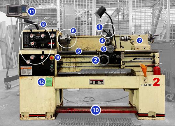
Lathe
- Tool Post - Securely holds cutting tools and allows their angle to be adjusted
- Carriage - Moves tools toward/away from the workpiece on the z axis
- Cross slide - Moves tools toward/ away from the workpiece on the x axis
- Compound slide - Additional axis that can be set an an angle to move the tool in an additional direction (usually for cutting tapers)
- Ways - the rails on which the carriage, cross slide and compound slide move
- Three jaw chuck - Holds the workpiece and spins with the spindle.
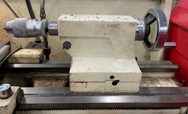
- Tailstock - Holds drills and live center
- Control Panel - Adjust speeds, feeds, and e-stop
- E-Stop Button - Cuts power to the machine in an emergency (also important to press if working with hands on/in the jaws or spindle)
- Emergency Foot Brake - Cuts power to the machine in an emergency
- Digital Readout - Provides precise position of the carriage and the cross slide
- Maintenance Tag - Manually tracks the usability status with color-coded cards
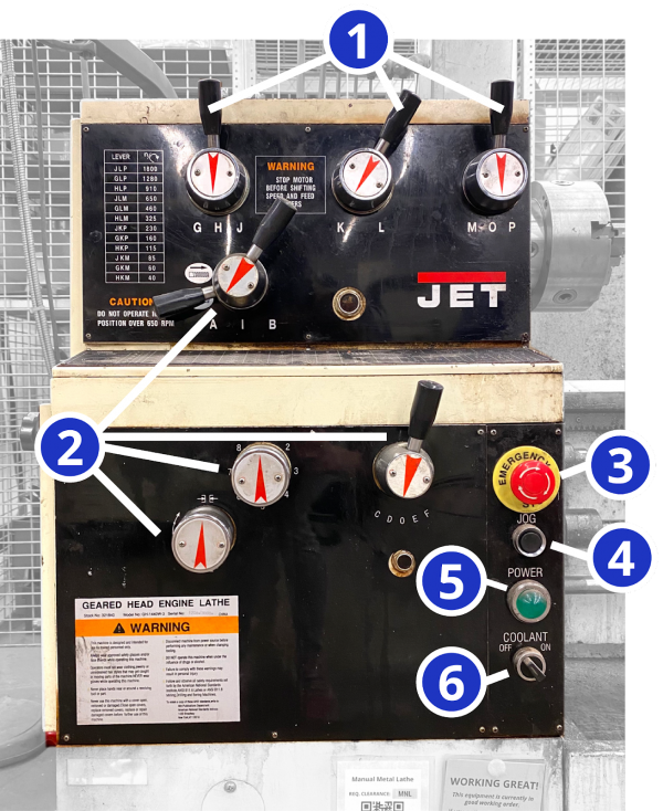
Control Panel
- Speed Adjustment Levers - Set the speed at which the chuck spins
- Feed Adjustment Levers - Set the speed at which the autospeed moves the carriage or cross slide.
- E-Stop Button - Cuts power to the machine in an emergency (also important to press if working with hands on/in the jaws or spindle)
- Jog Switch - Press and release to advance spindle momentarily
- Power Indicator Light - illuminated whenever lathe has power
- Coolant On-Off Switch - turns coolant pump on and off
Tool Checklist
- On the lathe top
- Chuck Key
- 1/2“ wrench
- 3/4” wrench
- 1-1/8“ wrench
- Chip brush
- Oil
- Cutting Fluid
- In the tool cabinet
- Carbide facing / turning tool
- Parting off tool
- Drill chuck
- Center drills / drills
- Boring bar
- Live Center
Tool Safety
The lathe is a joy to operate, but it must command your full attention. Keep in mind that it can shred steel (which is much harder to shred than humans). It is powerful and can result in serious injury if used improperly.
Personal Protective Equipment
⚠️ At the manual lathe safety glasses and closed-toed shoes are also required.
⚠️ All hair, clothing and accessories should be secured close to the body. Necklaces, hoodie drawstrings, hair, etc. can all be pulled into the machine resulting in injury or death. Roll up sleeves and tie back long hair.
🚫 Do not wear gloves or rings when working on the lathe. Much like loose clothing, these can get pulled into the lathe, resulting in injury or death.
Common Hazards
- The lathe can drag the user in by getting hair, clothing and accessories wrapped around the work piece or chuck.
- Always secure dangling clothing, hair and accessories.
- Remember to roll sleeves securely to elbows
- Never wear gloves while operating
- Pieces of the workpiece are cut away in spiraling chips. These chips can be sharp and hot. They can also wrap around the chuck and workpiece creating a swirling tornado of sharp metal if not cleared away often enough. That tornado can cut you or worse, catch on your clothing or hair and pull you into the lathe.
- Always wear safety goggles and appropriate PPE
- Practice good chip management!
- Break chips frequently by briefly pausing the cut.
- Clear chips away from the chuck
- The lathe operates using high torque. Unsecure objects (like if the chuck key is left in the chuck!) can be flung out of the machine at high speed or dragged into the rotation, possibly resulting in injury or death.
- 🚫 NEVER LEAVE THE CHUCK KEY IN THE CHUCK
- Never reach over the chuck or lean on the machine
- Never turn the lathe without something gripped in the chuck
- Wait for the spindle to stop before releasing your focus
General Safety Precautions
- Note that the lathe has two emergency stops: the button and the foot pedal. Activating these stops will cut power to the machine, but will not stop it immediately. The lathe has considerable momentum and it will continue to spin for several seconds after the stop has been activated.
- Keep the E-STOP engaged when you are installing your workpiece or tools. You don’t want the machine to start if your hands are in it.
- Never turn the lathe without something gripped in the chuck. Make sure all three jaws of the chuck are closed on the workpiece. Keep as little material as possible exposed. It will reduce bending and vibration. If you must have a large amount of material exposed, consider using the live center to help support your workpiece.
- Wait for the spindle to stop before speaking to the operator.
- Look and listen. If something seems weird, it is weird. Stop and reassess if you hear screeching, thumping or vibrating, or smell something smoky or burning.
MATERIALS
Allowed Materials
General Use Materials that are permitted for use on the equipment. Use of tool-safe materials outside of that scope would require a Special Setup arrangement with staff in advance of your visit.
- 👍 Non-hardened metals
- 👍 Mild Steel
- 👍 Aluminum
- 👍 Stainless Steel
- 👍 Brass
- 👍 Delrin
- 👍 Machinable Wax
Prohibited Materials
- 🚫 Hardened Steel - Do not cut hardened steel on the lathe (it is harder than your cutting tool)
- 🚫 Wood - Do not cut wood on the metal lathe as there is a more appropriate lathe available in the woodshop.
Safety1
lipsum sorem
Tool Care
Care1
lipsum sorem
Initial Setup
Setup Checklist
- Secure clothing and hair / remove accessories / put on safety goggles
- Check that all tools are present
- Clean the ways and mating surfaces
- Oil the ways
- Ensure the chuck is tightly attached to the spindle
- Unlock the E-stops
- Set speed
- Load the workpiece keeping as little material as possible exposed, use a live center if a large amount of exposure is necessary.
- Remove the chuck key
- Power on the machine and begin operation
Consumables
Cutting tools are considered consumables. You may find cutting tools already installed on the tool block, but they may become dull and need replacing. You may want to purchase your own set of the following:
Clean Ways & Mating Surfaces
Dirty ways can get scratched which will prevent the lathe from moving smoothly/accurately. Always brush off any chips that are on the ways (the rails that the tool carriage, cross slide and compound slide ride on).
When installing a chuck, make sure to clean all visible mating surfaces. If it is a shiny surface (not painted or black), it needs to be cleaned before starting.
Hit the e-stop to prevent the machine from turning on with your hands in it. Use the chip brush or your fingers to gently remove any chips that are in the spindle or on any of the mating surfaces.
Oil the Ways
Oiling the ways keeps the machine moving smoothly and accurately. The ways should be oiled each time you set up the machine, and any time during operation that you notice that the ways do not have a coating of oil.
There should be a can of oil at the lathe labeled “Ways Oil”. This oil is quite viscous and sticky, and is designed not to drip off of surfaces to which it is applied. Please leave this oil at the machine, and do not use other oils on the ways.
There are small brass inserts with a spring-loaded ball bearing on the carriage(2) and cross slide(3). Push the tip of the oil can against the ball bearing until the tip rests firmly inside the depression. Pump the oil can’s handle until two squirts of oil have been put in. This fills an internal reservoir that will continually lubricate the ways as you move the carriage and cross-slide during your turning operations.
If chips build up on the ways, please wipe them off to prevent scratching and premature wear to the ways.
Secure the Chuck
The three jaw chuck is the fastest and easiest way to hold onto parts. If the workpiece is very small or requires high precision, the collet_chuck may be preferable.
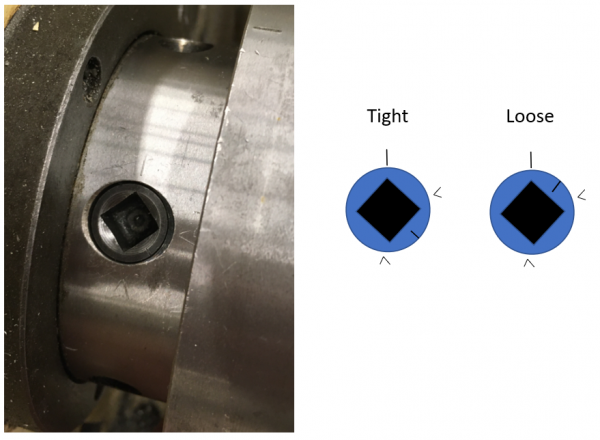
The chuck is secured using three retained bolts (they cannot be removed).
- Ensure the hatch line on each bolt is between the two Vs etched on the chuck as shown below. If it is not between the Vs it is not tight.
- It is good practice to loosen and tighten each of the three bolts before beginning use even if they look tight at first glance. Trust, but verify!
- 🚫 DO NOT LEAVE THE CHUCK KEY IN THE CHUCK!
- Set the Speed
Never turn the lathe without something gripped in the chuck.
Always ensure that all three jaws of the chuck are closed on the workpiece. Keep as little material as possible exposed. It will reduce bending and vibration.
If you must have a large amount of material exposed, use the live center to help support your workpiece.
Set The Speed
The speed of the lathe should be set according to the material you are cutting, the size of the material, and what type of cutting tool you have (carbide or HSS). Never change the speed while the machine is running.
The recommended settings should be considered upper limits. There is nothing wrong with cutting at lower speeds as you get the feel for it.
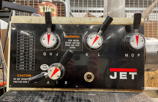
Select your speed (see common settings) and finding the closest match on the table located on the upper left portion of the lathe:
Turn the top three knobs to match the letters indicated by the table. The lathe is set to 115 Rotations Per Minute (RPM) with the knobs set to HKP. (Note O indicates neutral and the lathe won’t spin if the third knob is set to O).
Common Settings
The turning speed of the lathe depends on the material you are cutting and the diameter of the workpiece. Large workpieces need slower speeds because their surfaces move faster relative to the cutting tool. Soft materials can be cut quickly, but hard materials should be cut slower.
A few example speeds for common materials and diameters are listed below: (all assuming a High Speed Steel (HSS) cutting tool)
| Diameter | Ideal Speed for aluminum (RPM) | Recommended speed (RPM) | Ideal Speed for Steel (RPM) | Recommended |
|---|---|---|---|---|
| ¾ inch | 2546 | 1273 | 407 | 204 |
| 1 inch | 1910 | 955 | 306 | 153 |
| 2 inch | 955 | 477 | 153 | 76 |
| 3 inch | 700 | 350 | 102 | 51 |
Note the recommended speed is ½ of the ideal speed. The ideal speed is what would be used by a machinist if they had a coolant flow, sharp cutting tools, etc. For most hobbyists the ideal speed is much higher than needed. You can always run the tool slower if you feel intimidated at higher speeds.
See additional resources to find a speed calculator for different materials or diameters.
REMEMBER YOU CAN ALWAYS TURN SLOWER THAN THE CALCULATED SPEED!
Basic Operation
Operation Checklist
- Setup
- Power on the machine, leaving the E-Stop engaged
- Set the direction of rotation
- Load and align tooling
- Set the origin
- Twist E-Stop button to enable the lathe (lifting the emergency stop pedal with toe if it still does not start)
- Begin cutting
- Cleanup
Set Rotation Direction
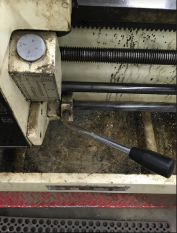
This lever on the lower right of the carriage acts as the power switch for the spindle. To turn the machine on, push the handle slightly towards the tail stock to unlock it from its off position, then move it up or down to turn the spindle on in the desired direction. Release the handle when you have moved it to its full extent and the machine has turned on. If the machine does not turn on, return it to its off position and check the e-stop and foot pedal switch.
To make the jaws spin toward you, lift up on the spindle control handle.
To make the jaws spin away from you, push down on the spindle control handle. For the vast majority of operations you will lift up. You want the material you are cutting to come down onto the cutting tool where the cutting surface is sharp.
To stop the spindle, move the handle to its off position without pushing the handle in towards the tail stock. It will naturally fall into its locked off position. 🚫 Never move the lever from one direction to the other without first moving the lever to its off position and waiting for the spindle to come to a complete stop.
This lever should be used to stop the lathe during normal, non-emergency usage instead of the e-stop.
Load Tooling
Select your tool and tool holder. There are tool holders with tools already installed in the black drawers. Be sure to check that the tool is securely attached by the screws in the tool holder. Don’t assume the person before you installed them correctly.
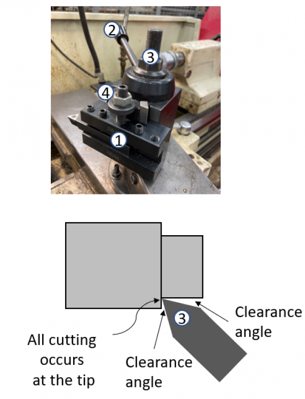
Once the tool is inserted into the tool holder, load the tool holder onto the tool post shown below:
Tool Post Setup
- Place the tool holder onto the dove tail of the tool post.
- The locking handle tightens the dove tail to hold the tool holder in place. Leave it loose when starting setup.
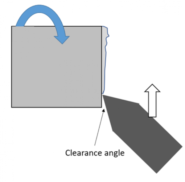
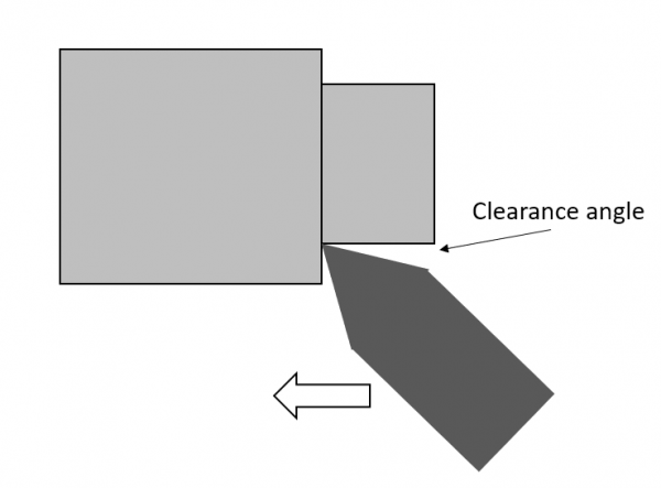
- Set the angle of the tool tip by loosening the top bolt, moving the tool block and retightening. Be sure there is clearance at the front and back of the cutting tool for chips to evacuate. All cutting should occur at the tip, not on the sides of the cutting tool.
- Set the height of the cutting tool by adjusting the thumb screw and locking it in place with the top nut.
- Lock the tool holder into position using the lock handle.
Checking Tool Height
- Move the carriage up to your workpiece and set the height as close to the center of your part as you can.
- Lock it down using the lock nut and the dovetail lock handle.
- Start the machine at a low speed and face a tiny bit of material off the front of the workpiece. If you are high or low you will see a “belly button”.
- Adjust your tool up or down depending on the location of the belly button relative to the cutting tool.
- Keep adjusting until the tool is centered and no detectable belly button appears. (Remember that the height of your tool will change slightly after you lock down the dove tail, so you may need to adjust a couple of times.)
Set the Origin
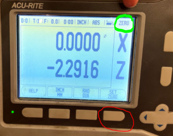
The digital readout can be used to provide an accurate measurement of the position of the carriage and the cross slide. It has lots of functions, but setting the tool position to zero is the most important. To set the zero position of the carriage and cross-slide, follow the following steps:
- Make sure the readout is in zero mode. The top right of the screen should say “zero.” If it says “set” instead, hit the mode button (circled in red) until the top right reads “zero.”
- Move the carriage and cross slide to your desired zero point and hit the set buttons (circled in blue) to set their positions to zero. (Carriage is Z and the cross slide is X.
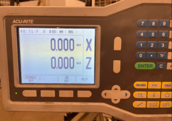
- If the screen looks as it does below, hit “no ref”.
Types of Operations
Facing
Facing is the act of creating a flat surface on the front of the workpiece or a shoulder along its length.
- Touch off on the front of your part
- Back off using the cross slide
- Move in .020” or so on the carriage
- Set Z0 on the digital readout
- Slowly move the cutting tool across the face until you reach the center
- Back off using the carriage so you don’t ruin your surface finish by tracing back over the part (only on the finishing pass)
- If facing to check for centering:
- Check the front of your workpiece for an “outie belly button.”
- If there, move your tool up to the belly button to see if it is high or low.
- Adjust the nut accordingly and repeat.
Turning
Turning is performed to change the diameter of the workpiece with high precision.
- Touch off on the side of your part
- Back off using the carriage
- Move in .020” or so on the cross slide
- Set X0 on the digital readout
- Slowly move the cutting tool across the outer diameter until you reach the end of your shoulder.
- Back off using the cross slide so you don’t ruin your surface finish by tracking back over the part. (This will also face the front edge of the shoulder)
Chamfering
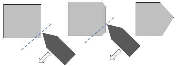
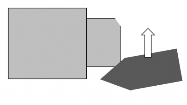 Chamfering creates a slanted edge on the face of your part. It is useful for breaking sharp edges and for making parts that insert into holes more easily without jamming.
Chamfering differs from facing and turning because it uses the side of the cutting tool rather than the tip. Adjust the angle of your tool block and drive the cutting tool across your workpiece using the cross slide.
Drilling
- To insert drill chuck: extend the tailstock out past the 10 mark
- Push the drill chuck in a make sure it is secure (rotate it if it doesn’t slide all the way in)
- Do not retract past the 10 mark or it will eject the chuck
- Slide the tailstock up close to your part and lock it into position using the handle on the back side. If you don’t lock it down, the tail stock may slide backwards as you drill.
- Always drill with a center drill first. This will keep your drill in the center of your part. If you don’t use a center drill, your drill may walk and damage the part or break the drill.
- Drill with a pecking motion to clear chips and allow the workpiece and drill to cool. (keep an eye out for little pieces of chips welded to the drill. Stop and chip them off if you see them) Be sure to bring the drill all the way out of the workpiece when you peck to clear chips and allow the bit to cool. Cutting fluid is highly
recommended for any metal, but absolutely essential for steels.
Tapering
Tapering allows you to create an angled cut on your part. It is similar to turning and facing in that the cut is performed with the tip of the cutting tool. The main difference is that the cut is performed using the compound slide.
- Set the angle of the compound slide
- Move the tool in just past the outer diameter
- Use the compound slide to make a cut
- Retract the compound and move in with the cross axis.
- Repeat until your final cut at which point you will retract with the man carriage away from your part to protect the finish.
Parting Off
Parting off requires a specific tool and allows you to cut parts to a very accurate length.
- Load the cut-off tool into the tool post
- Loosen the tool post and use the flat front of the 3 jaw chuck to square the cut-off tool to the spindle.
- Tighten down the tool post when there is no gap between the front of the jaws and the tool
- Touch off on the front side of your part and set the zero position on the digital readout.
- Move the cutting tool to your cutting position. Remember the cut-off tool is 0.125” wide, so move the axis an extra 1/8” to make your part the right length
- Slowly drive the tool into your part using the cross slide (1/4 the speed you would use to face or turn)
- Remember to back off occasionally to clear chips and cool the tool. Cutting fluid is recommended.
Cleanup
Cleanup Checklist
- Power off the lathe
- Return all tools
- Brush chips from top to bottom
- Empty the chip tray by removing and dumping and/or vacuum it out
- Wipe all chips and debris from mating surfaces (includes ways and inside the chuck attachment if you used the collet attachment)
- Oil the ways
- Ensure 3 jaw chuck is secured
- Ensure all axes are unlocked
- Unlock the Estop
- Note any maintenance needs or concerns on the tag and at protohaven.org/maintenance
Maintenance Requests
If you encounter any of the issues listed in the Inspection area or have any other issues with the printer not working properly
- Update the physical Maintenance Tag at the machine
- 🟢Green can be used without issue
- 🟡Yellow can be used withcaution
- ⛔Red cannot be used without hazard to either the user or the equipment
- Record issues at http://protohaven.org/maintenance. This notifies our staff and volunteer maintenance crew of any issues.
Troubleshooting
The machine doesn’t turn on
The e-stop is engaged
- Twist the E-stop button until it pops
- Lift the E-stop foot pedal with your toe and try to turn the machine on again
The power button on the back is off
- Turn on the power switch on the back of the machine.
The cut has a poor finish (wavy)
The speed of the jaws is too low compared to your tool’s travel speed
- Move the carriage or cross slide slower
- Speed up the spindle
The work piece is deflecting
- Too much material is out of the chuck—shorten up. If not possible, use a live center to support the part.
- Make smaller cuts to reduce the force on the workpiece
The spindle won’t move when you lift the spindle control handle
The spindle is not in gear
- Move the speed selection knobs and make sure you hear/feel them click into place. If they don’t click, rotate the jaw while turning the knobs. (never change speed while running the spindle)
The E-STOP is on
- If no electrical activity is heard the handle is lifted, the e-stop is on.
- Twist the E-STOP button and release the emergency stop pedal
The power button on the back is off
- Press the power button on the back of the machine
Special Setups
Collet Chuck
When cutting very small diameter material, or when extreme precision is needed, it may be beneficial to use the collet chuck as opposed to the three jaw chuck.
Live Center
When cutting long material, the end of the workpiece will need to be supported to prevent bending. This will require drilling a small hole in the end of the workpiece, installing a live center into the tailstock, and inserting the live center into the hole. Check out a video on the subject.
Additional Resources
Clearance Rubric
Protohaven’s Clearance Rubric for Manual Metal Lathe
Where to buy consumables
McMaster-Carr is an easy (and incredibly fast) resource for lathe tools and raw materials. https://www.mcmaster.com/ (Part numbers are listed in the table in the consumables section)
Helpful Tutorials
How to use a live center: https://www.youtube.com/watch?v=8x6maER5qr0
Speed Calculator
Spindle speeds can be calculated here. Look up the feet-per-minute speed for your material and then enter the diameter of your part to calculate how many rotations per minute it needs to spin. Remember to divide by 2 as these speeds will be ideal speeds for machinists under ideal conditions : https://littlemachineshop.com/reference/cuttingspeeds.php (More info in the Set Speed and Common Settings Sections)
Staff Use
| ⚠️ AUTHORIZED MAINTENANCE GROUP ONLY |
If you are part of the maintenance group please log on to the #maintenance channel of our Discord server to:
- Perform a Maintenance Action
- Request a Maintenance Purchase
- Review complete Maintenance Logs for each machine
- Generally chit-chat about maintenance
Regular Maintenance
Lubrication, manual p. 10 Coolant Prep, manual p. 12 Parts List & Exploded Views, manual p. 22-64
Technical Support: 1-800-274-6846 Replacement Parts: https://store.jettools.com/metalworking.html
